Pictures and CSV of logic level dumps of an unmodifed E360DN added. Legacy Win7 driver and Lexmark driver captured |
||
|---|---|---|
| build | ||
| kicad | ||
| ols-dumps | ||
| samples | ||
| src | ||
| .gitignore | ||
| LICENSE | ||
| makefile | ||
| README.md | ||
haxmark
This project has the goal of modifying a Lexmark E360d/E360dn for direct PCB printing.
It is based on this great instructable by mlerman, which uses a Lexmark E260d. The E360d is nearly identical in its hardware. Anyhow, I found out that there are some software differences between E260d and E360d. This is why a designed a new MCU board for simulating the printer's timings.
Project status and performance
The project is in a "beta" state, meaning I can successfully print on PCBs with good quality but occasionally, my printer doesn't quite like the signals generated by my controller board and stops with a paper jam error until it is hard-rebooted. This seems to be unpredictable and the behavior even differs from time to time. The actual cause of these problems is unknown to me at this point (needless to say, the MCU software is quite beta, too).
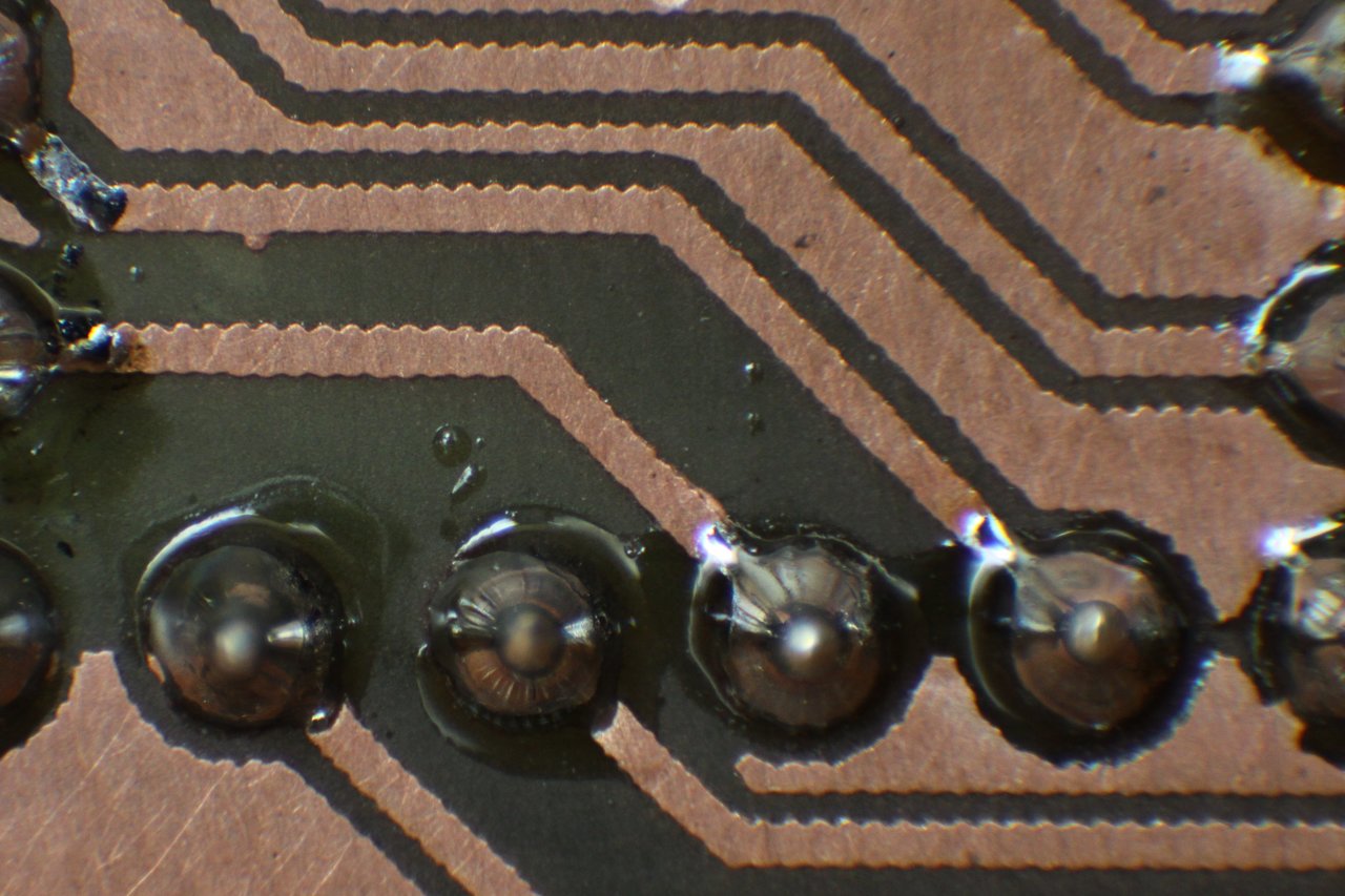
The results are quite good: A minimal trace width of 5mil and a minimal clearance of 10mil are no big deal.
Modification
Some notes before you modify your printer
I strongly recommend that you test your printer in an unmodified state with exactly the driver and printer settings you intend to use it with to print on PCBs. I found out the hard way that the behavior and the timing differ from driver to driver. It is definitely a good idea to make a dump of the interesting signals (operator panel line, manual paper feed sensor, paper in sensor, exit sensor) with a logic analyzer to get the exact timing of your printing setup so you can adjust the timing settings in the MCU board's source code. I included a dump made with logic_sniffer and my settings. I use the printer with linux and this PPD file with 2400dpi image resolution. I have not used it with Windows, so if you plan to do that, better check the printer's behavior in detail before making any modification.
Differences to the E260d
The main hardware difference between E260d and E360d is the use of a different operator's panel. But in the software there seem to be quite some:
- The E360d does not, unlike the E260d, pull in a piece of paper stuck into its front. Instead, it stops with a paper jam message.
- When starting a print, the printers motor runs for a while before it is stopped and the user has to confirm he has inserted a piece of paper into the manual feeder by pressing the tick button. Then, the motor starts running again and a few seconds later, a clutch is activated and the paper is finally pulled in. If the paper is inserted significantly before the clutch is activated, the printer reports a paper jam. Note that some drivers seem to omit the first motor running phase (this modification should work with both variants)
Hardware modification
The hardware modifications are mainly the same as in the original instructable. But, because the motor directly pulls in the carrier, an additional clutch is needed to keep the rollers stopped unless the carrier actually should move. The printer provides a solenoid, which is able to block the rollers, on its left side. Cut the low-side cable at the printer's controller board and connect it to the new MCU board. Leave the other end connected to 24V. The MCU board also needs a connection to a hall sensor of the motor in order to be able to check if it is running. I tapped the lowest pin on J17, but any of the three sensor lines should work. Just be sure that you do not connect the MCU to one of the motor windings (the three wires with the ferrite bead over them), as they are driven with 24V.
I made also some smaller modifications:
- I use a 18cm wide and 30cm long carrier. The 60cm long carrier proved to be way to long for me.
- I swapped the forked light barrier "new paper in sensor" for a reflective sensor (SFH900-2). This way I can use a piece of tape on the carriers bottom instead of a hole. If you use the original approach, you have to invert the signal in the AVR's source code.
New MCU board
My new controller board monitors the motor in addition to the tapped line from the operator panel, which by the way is a serial data line and gets toggled with every key press, at the startup and every once in a while. I also included three status LEDs, which are not really useful at the moment, and an RS232-TTL port for debugging purposes, which is unused so far. The crystal is actually optional, just make sure you change the fuse bits in the makefile if you do not solder one in.
Printing
The printing process is straightforward:
- Hit "Print" in whatever program you design your PCBs with
- Wait until the printer's motor stops running
- Put the carrier with the bare PCB on it in
- Press the tick button on the printer and watch it print
- Treat the PCB in acetone vapor (as described in the original instructable) and etch